A Sunrise Alarm Clock
I built a sunrise alarm clock so I wouldn’t need to wake up in the dark during the winter time when the sun rises very late. This was the first PCB I had ever made and I had a lot of fun with it. The hardware and firmware is all on github.
The board is powered by an Atmega328 and has, in no particular order:
- Three power transistors to control the RGB channels of an LED strip
- A power regulator so it can be powered by a 12V wall wart
- A real time clock with a battery backup to keep track of the time
- No surface mount parts because I wasn’t sure I could solder them
- Dope sunrise art
Contents
Hardware Development
In the Beginning
I started this project with a cheap clone of the Arduino pro mini driving an LED strip, and the first time I left it on overnight it burned out the power regulator. This probably would not have happened to a legit Arduino pro mini, but the cheap clones have to make compromises in the design to lower costs, and the power regulator is a good way to save on component costs.
I was also keeping track of the time using the Atmega’s clock, but this isn’t the best approach because if the board lost power for any reason then it would lose the time. Maybe for a microwave that is ok, but not for an alarm clock (Why don’t microwaves save the time? An RTC only costs a few dollars).
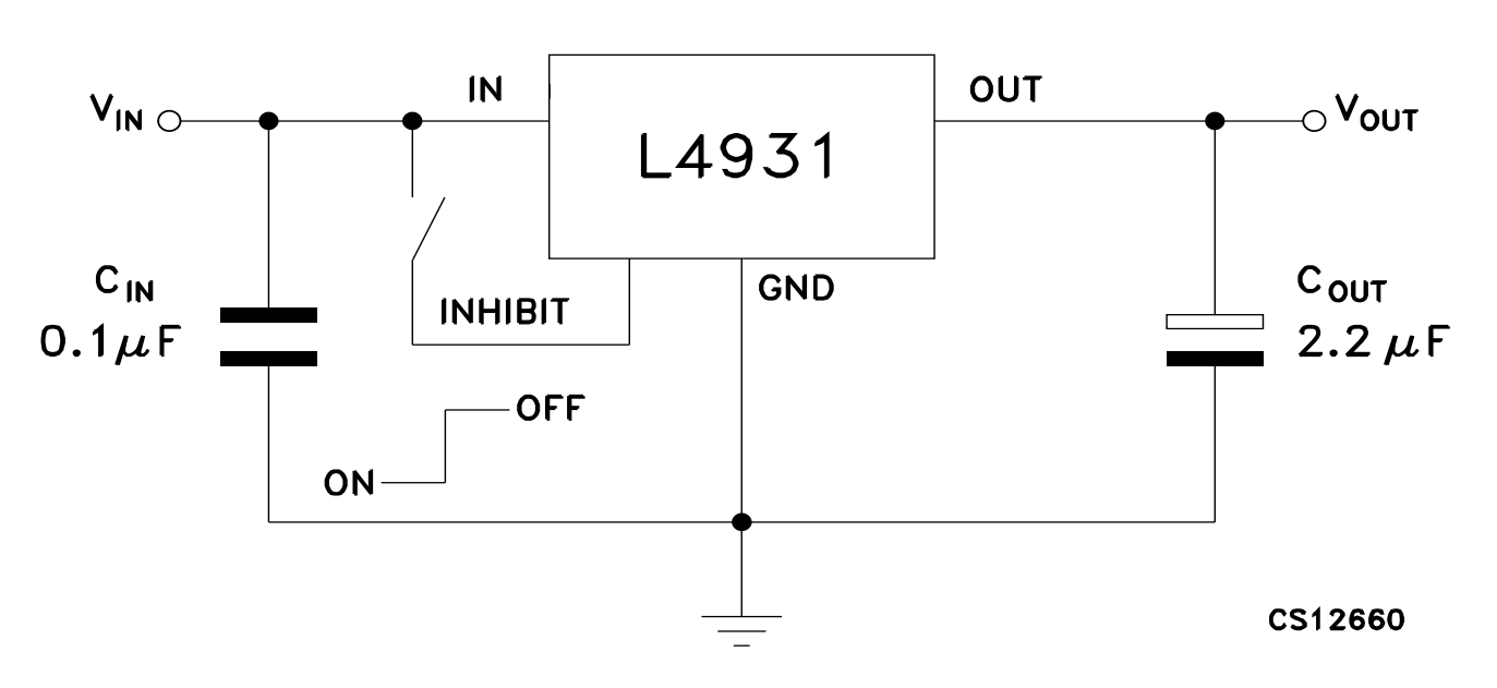
My second attempt used a real time clock (RTC) module I bought from Adafruit, and a better power regulator. Figuring out how to use this power regulator was straightforward because its datasheet has an example circuit that was exactly what I was trying to do. All this assembled on a breadboard worked great! The LEDs powered up at the scheduled time, but the barrel jack was really easy to accidentally pull out of the bread board, so I decided I needed to solder some components into a circuit board.
The Circuit Board Design
My first thought was that I should make a board with the barrel jack, output transistors, better power regulation, and sockets for the Arduino and the RTC module. The RTC module communicates over I2C, but the position of the I2C lines on the Arduino aren’t on the standard set of pins that fit in a breadboard, so any Arduino I could plug in wouldn’t be compatible with a breadboard anymore.
It was at this point I realized there were only 15 components on the Arduino board and I was going to need my own copies of 4 of them for power regulation. The schematic is also open source, so I thought it would be more fun to build my own PCB with the components I needed from the Arduino and RTC modules as well as all the output and power regulation circuitry.
I started with the Arduino pro mini schematic and made changes and additions until it had all the things I needed. I knew I wanted to use the L4931 regulator and a barrel connector to provide power to the board, so I subbed those into the power regulation section of the Arduino’s schematic. The stabilization caps on the Arduino design are larger than those suggested by the L4931 datasheet, so I used the larger ones just to be safe. I have since learned that the smaller ceramic capacitor is used to smooth out higher frequency variations in the output voltage. It has a much lower equivalent series resistance (ESR) than an electrolytic capacitor so it can respond faster, but large ceramic caps are expensive, so the electrolytic capacitor smooths out any low frequency noise on the cheap and the ceramic cap takes care of the high frequency noise. There is also an optional power indication LED I chose not to solder because I don’t like lights I can’t turn off on things in my bedroom.

The design of the RTC breakout from Adafruit is not open source, but the datasheet for the DS1307 is excellent, and has an example on the very first page! I sure do appreciate good documentation. There is one additional component on the breakout board I got from Adafruit, but I think it is just a power stabilization capacitor. This clock will keep the time using the backup battery if main power is lost, so if I unplug the board, or the power goes out I don’t need to reset the clock. The two pull-up resistors on the SDA and SCL lines are required by the I2C spec. The 32.768kHz crystal is a requirement of the chip. This is a very popular speed for clocks because it makes counting seconds so easy because 32,768 is 215.

I replicated the setup I had on the original breadboard design for the high power output transistors. The gates are connected to PWM capable outputs on the microcontroller and provide a high capacity current sink for the LED strip when on. Most of the strands I’ve seen are powered off of 12V and use a common high voltage line, so this setup should be compatible with many LED strips. The pull down resistors on the outputs here prevent the LED strip from momentarily turning on when the microcontroller is reset. The Atmega328 sets all pins to input without pull up resistors when it is reset so the voltage at the mosfet gate would be left floating, potentially allowing it to turn on.

The rest of the schematic is the same as the Arduino board I was using. There is another power stabilization cap drawn very close to the microcontroller. In this case this means that the cap should be physically close to the microcontroller on the board to provide a very stable voltage for it to use. The microcontroller will probably use different amounts of current at high frequency, so this makes sense to me.
The other interesting bit of this part of the schematic is the reset hardware. There is a cap between the DTR pin on the programming header and the reset pin on the microcontroller with a pull-up resistor. This is so that if software fails to pull the DTR pin high again the board will still reboot after charging the capacitor through the pull-up resistor. The values of the capacitor and resistor here have been tuned so the board is only momentarily off and can talk to the computer properly even if there are bad drivers for the programming cable.

Circuit Board Layout
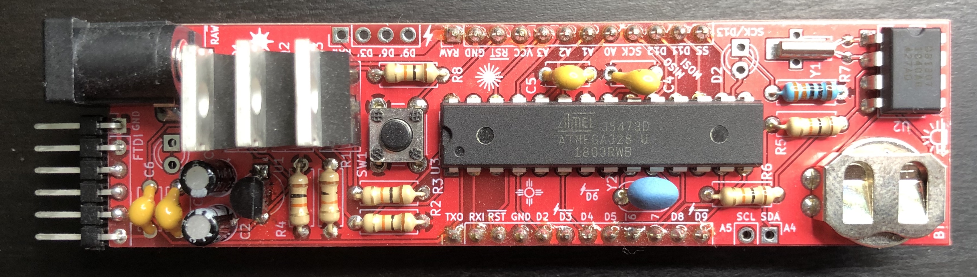
I decided to use only through hole parts because I wasn’t sure I had the skill to solder surface mount components. I also wanted to make sure I could debug and expand the design, so I wanted all the standard Arduino pins to be accessible if I plugged it into a bread board. All this means that the board is very skinny so it would fit on a bread board and in order for there to be any room left on the bread board it has to hang way off the end.


The Firmware
Color Profile
When I first started thinking about a sunrise alarm clock I thought it would be neat to have it run through the colors of the actual sky during a sunrise. Surely somebody has collected such data. As I tried to find a dataset I discovered that “the sky at sunrise” isn’t a very precise idea. What angle above the horizon? East, West, straight up, or some other azimuth? A single point or the average color over an area? Are there clouds? If so where? Is there haze in the air?
I decided this was too much and I should instead choose a color profile that seemed natural without any relation to The Real Sky. I settled on the color of a perfect black body radiator because it goes from red to “white” which seemed nice, and there is a nice physical metaphor with the light source warming up for the day. I got some data about hue for different temperatures here. The colors in this dataset were converted using a D65 whitepoint, which is why I think there is a kink in the plot around 6500K. I played around with this data a bit and decided I liked the look of a ramp from 1000K up to 4500K. This leaves the lights a little more yellow than a true white which I find nice in the morning.

The intensity of a true blackbody goes up way too fast to be a satisfying light, and since our eyes respond exponentially, I thought an exponential brightness curve would look nice. The lights need to start off and end at fully bright over some period of time, so the brightness function \(B(t)\) will need satisfy \(B(0)=0\) and \(B(1)=1\). By shifting the exponential function down by one and then using horizontal and vertical stretching I can ensure that our needs are met while still leaving a parameter free for the steepness of the curve. The exponential function with a vertical shift of -1, a vertical stretch of \(k\), and a horizontal stretch of \(a\) is \(B_k(t) = k \left( e^{a t} - 1 \right)\). Solving \(B_k(1) = 1\) to gives \(a = \ln\left(\frac{1}{k} + 1\right)\), leaving \(k\) as the single steepness parameter. The full brightness function is then
\[B_k(t) = k \left( \exp \left( t \ln \left( \frac{1}{k} + 1 \right) \right) - 1 \right)\]
Normalization
The blue LEDs on the strip I have seemed much brighter than the green or red channels, so I knew I needed to tone them down, but by how much? To determine this I took a picture of a white sheet of paper lit by the LEDs at full power and then looked at a histogram of each color channel.

Normalizing the green and blue channels to the max output of the red LEDs means that “full power” for the green channel should be \(\frac{87}{96} \cdot 255 = 231\), and for the blue channel \(\frac{87}{179} \cdot 255 = 124\).
High precision PWM
The difference between the lights being off, and being on at 1/255 power is pretty jarring. At higher powers the steps become less noticeable, but the first few steps are very clearly visible. Fortunately, there is a 16 bit clock on the Atmega328 and it can control the PWM output on pins 9 and 10, providing steps too small to notice. I didn’t know this when I fabricated the boards, so I got really lucky that one of the LED channels is wired to pin 9! Unfortunately, the Arduino environment doesn’t make it easy to access this functionality (it looks like there is some work to make that better, but not for AVR based boards), so I had to directly set values of the control registers. This stack overflow answer got me started nicely and I filled in the rest of the code by replicating the Arduino source and the taking a look at the relevant parts of the Atmega328 datasheet.
void setupPWM16() {
  TCCR1A = _BV(COM1A1) | _BV(COM1B1)  /* non-inverting PWM */
    | _BV(WGM11);                     /* mode 14: fast PWM, TOP=ICR1 */
  TCCR1B = _BV(WGM13) | _BV(WGM12)    /* other bits for mode 14 */
    | _BV(CS10);                      /* no prescaling */
  ICR1 = 0xffff;                      /* TOP counter value */
}
This setup function sets a bunch of flags that control the output of pins 9 and 10. These pins are internally called PB1 and PB2, and can optionally be driven by output compare 1A (OC1A) and output compare 1B (OC1B). The 1A and 1B suffix is used throughout to refer to these two outputs. WGM is the Waveform Generation Mode, and it is being set to mode 14 which is fast PWM with the maximum counter value controlled by ICR1. We want the steps to be as small as possible, so we will use the full 16 bits of the counter by setting the max value to 0xffff. CS is the Clock Select settings, and it is set so there is no prescaling on the timer because there is no reason to not have the PWM cycles happen as fast as possible.
void analogWrite16(uint8_t pin, uint16_t val)
{
  pinMode(pin, OUTPUT);

  // PWM outputs cannot be fully on or off, so use digitalWrite instead
  if(val == 0) {
    digitalWrite(pin, LOW);
  } else if(val == 65535) {
    digitalWrite(pin, HIGH);
  } else {
    // Calls to digitalWrite overwrite some things, so make sure to reset them
    switch (pin) {
      case 9:
        _SFR_BYTE(TCCR1A) |= _BV(COM1A1);
        ICR1 = 0xffff;
        OCR1A = val;
        break;

      case 10:
        _SFR_BYTE(TCCR1A) |= _BV(COM1B1);
        ICR1 = 0xffff;
        OCR1B = val;
        break;

      default:
        return;
    }
  }
}
This is a 16 bit version of the standard Arduino analogWrite function. Setting OCR1A to 0 won’t turn the PWM all the way off because of the way it is implemented internally, so in order to turn off the pin we need to switch it to digital mode. When we do that we end up stomping on the value in ICR1 and TCCR1A, so we need to set those if we want to update the PWM output.
void writePWM(uint8_t pin, double value) {
  if(pin != 9 && pin != 10) {
    analogWrite(pin, ratioToRange(value, 256));
  } else {
    analogWrite16(pin, ratioToRange(value, 65536));
  }
}
I didn’t want to keep track of which output channel was on the high resolution PWM, so I wrote this wrapper function that writes the proper PWM value based to the pin based on a floating point value from 0 to 1.
With all this setup, the red channel, which comes on first, can use the high resolution timer, which makes everything look much better. There is still a noticeable step when the green light goes from off to its lowest brightness, but there isn’t anything I can do about that without redesigning the board.
Wishlist
After using this for a while these are some features I wish it had:
- A better UI. Setting the wake up time or resetting the clock requires a firmware flash which … uhh, encourages you to have a healthy regular sleep schedule 🙃 A single button that could reset the time, or do a snooze, or turn off the lights would be nice.
- Mounting holes on the board. There isn’t a great way to put this thing into a case if I had one.
- A case. It is currently just sitting on my floor. Not a great spot for electronics to stay safe.
- Better interfacing with the LED strip. Terminal blocks, or some other type of convenient connector.
- High res PWM on the other channels. There is a pretty noticeable change when the green channel comes on, so it would be great to use a high res timer for that as well. To get high res timers for all three channels I would have to use something other than the Atmega328, which would probably be a good idea anyway.